Today was a beautiful day outside: sunny and in the 60s. At the same time Laura was handling the kids all afternoon in exchange for my doing the same yesterday, and normally that would send me straight to the basement without a second thought, except that it was such a nice day. I took a look around the layout room and decided that today was the day to build some fascia, and since that required the use of my saber saw, I'd share the dust and noise with the great outdoors. So I dragged out the sawhorses, clamps, saw, etc., and set up the IKEA tabletop I've had for 20+ years and which has gone from desk to occasional dinner table extension to its current roles (not simultaneous) as portable workbench top and bar for large parties. (Although that would be some party.)
You can see the already-cut 1/8" hardboard fascia sections on the bench, with leftover hardboard leaning against the house next to the 1x3 I used to ensure a (relatively) straight saber saw cut.
After some adjustments resulting from a decreasing adherence to the "measure twice, cut once" principle, I drew pencil lines on the back of each section to indicate where the fascia would meet the 1x3 frame, including a center line for the 1x3 itself. At this point I did not have a definite idea for securing the fascia to the benchwork beyond some kind of nut and bolt arrangement; since the section I was building would cover the front of the long shelf where the majority of remaining track construction will take place, and will also hold the control panel, I need to be able to easily remove and re-attach the sections for easy access. I set out for the hardware store with the only firm criteria being width (1/4 inch) and length (1 1/4 inches).
For some reason the nut/bolt/screw/washer section of the hardware store is the only time when coming face to face with an overwhelming variety of choices does not in fact overwhelm me. (In contrast, NEVER send me to the store for salad dressing.) A few minutes' perusal gave me the winning (for me) combination of carriage bolts (sturdy, smooth finish on exterior) and wingnuts (easy to remove), and I was on my way.
OK, so here is the part where I actually did have to confine my work to the basement, although in retrospect I could have probably done the hardboard drilling etc. on the patio. However, there was enough back and forth and minor adjustments necessary that it made more sense to stick to the basement. Nevertheless, by the end of the first round of work I had this to show for my effort:
This is not permanent, as I need to remove the remnants of the price sticker and paint the fascia a dark green, although I may wait to paint until after I fit the car-card boxes to the front. The card boxes will represent either industrial locations or yard tracks where freight cars are to be delivered or stored.
With the experience of the first section under my belt, the second section went in a bit easier, although I had to cut a shallow notch in the right-hand side to accommodate the top of the steel shelving unit supporting the engine terminal benchwork. You can also see that the lower edges of the fascia do not exactly line up, but I plan to address that with some form of soft border to reduce the possibility of catching oneself on the lower edge.
I can now get moving on the design of the control panel, which will fit on the right-hand section. The rest of the fascia will have to wait until the final terrain contours are established, although I may be able to do the work on the engine terminal section without too much trouble.
You may have noticed some odd things in the background of the last two pictures. In the first picture, you can see in the very corner of the layout a test platform for the Tam Valley servo control for the crossover turnouts; I need to build a sturdier version for the next round of testing (the first was promising). In the second picture, stacked in the corner are a couple of pieces of scrap foam with some scrap Code 55 track glued thereon. These are test platforms for track weathering, comparing (for the moment) Rail Brown (kind of greenish) and Railroad Tie Brown. I need to do a bit more testing before committing to a weathering method for the track, keeping in mind also that different kinds of track weather differently according to use. Sidings and yard tracks, for example, often appear more rusty than more-heavily-travelled and better-maintained mainline tracks.
Until next time!
Showing posts with label N scale. Show all posts
Sunday, March 11, 2012
Wednesday, January 25, 2012
Layout Update 24: Do Not Mock the Mockup
I managed to put in a few hours of work this weekend, primarily devoted to completing the transition section and the mainline. I gave the bridge a coat of Grimy Black to cut down on the shine, and test-fitted it to the abutments. The rural-side end of the approach to the bridge had to be trimmed back about a quarter of an inch, but everything fits together nicely now. I also cut and fit the wing retaining walls for the bridge abutments and test-fitted them in place as well. Finally, I measured and cut the remaining section of mainline track, and test-fitted it in place. Here's what all this test-fitting accomplished:
It is no coincidence that I have planned a road crossing right where the feeder lines make their unsightly appearance on the lower level track; the pavement and crossing should cover those up nicely.
The right-hand side of the bridge marks the boundary between two electrical control blocks, but with the lefthand approach track in place I realized that the bridge, even though not permanently affixed, was powered. The next decision was easy:
Here we see (albeit in poor focus) the train at about the farthest point it can go without hitting the pushpins holding the track in place, off to the lower right:
As one of my intended "signature scenes" I am very pleased with how even the rough mockup looks.
I should caution that I am not nearly at the stage where any of this can be permantly installed. The biggest priority is the scenery behind the bridge, which I need to do before installing the bridge. That's going to be quite the demonstration project; even though it is a very small area (no more than a couple square feet) it will involve modeling changes in elevation, water and vegetation. I have experience in exactly none of these things (although I've completed the basic landform by carving and shaping the foam board).
In a late-evening work session, I managed to get trucks and couplers installed on the remaining cars in my work train (crane car and its idler flatcar) and nine additional freight cars. I also want to tackle a steam locomotive (tender at least) coupler conversion so I can run a train behind my preferred type of motive power. However, I am trying to focus all available time and effort on the transition section, since my self-imposed goal is to have the mainline complete by the beginning of March. With my work train back in service, things should speed up!
It is no coincidence that I have planned a road crossing right where the feeder lines make their unsightly appearance on the lower level track; the pavement and crossing should cover those up nicely.
The right-hand side of the bridge marks the boundary between two electrical control blocks, but with the lefthand approach track in place I realized that the bridge, even though not permanently affixed, was powered. The next decision was easy:
Here we see (albeit in poor focus) the train at about the farthest point it can go without hitting the pushpins holding the track in place, off to the lower right:
As one of my intended "signature scenes" I am very pleased with how even the rough mockup looks.
I should caution that I am not nearly at the stage where any of this can be permantly installed. The biggest priority is the scenery behind the bridge, which I need to do before installing the bridge. That's going to be quite the demonstration project; even though it is a very small area (no more than a couple square feet) it will involve modeling changes in elevation, water and vegetation. I have experience in exactly none of these things (although I've completed the basic landform by carving and shaping the foam board).
In a late-evening work session, I managed to get trucks and couplers installed on the remaining cars in my work train (crane car and its idler flatcar) and nine additional freight cars. I also want to tackle a steam locomotive (tender at least) coupler conversion so I can run a train behind my preferred type of motive power. However, I am trying to focus all available time and effort on the transition section, since my self-imposed goal is to have the mainline complete by the beginning of March. With my work train back in service, things should speed up!
Wednesday, January 18, 2012
Layout Update 23: Extreme Train Room Makeover, Gravity Edition: The Reveal
I managed to put in a sustained burst of work over the three-day weekend (thanks Laura!) and can report that the train room renovation is essentially complete! With Fiona's help I put on two coats of sky-blue paint on the walls behind the layout on Saturday, then on Sunday I installed one of the two track-lighting (no pun intended, honest) units and began re-installing the ceiling tiles that had fallen. That brief period of work elicited the only real burst of profanity for the entire project, but it was of the highest quality and fortunately the sound did not carry clearly to the rest of the house via the ductwork.
Monday saw the re-installation of the remaining ceiling tiles without serious incident, with additional support provided by installing the brackets for the track lighting by screwing them to the overhead joists. I also drove a couple of screws through tile at a couple of suspicious spots for extra insurance. Finally, in the technically most fraught segment of work, in that I had never done it before and could have killed myself by skipping a step, I replaced the old light fixtures with the connections to the new lights.
Behold:
I will be the first to admit that is a bit darker and that the halogen lights do not illuminate the layout evenly. (As the second picture indicates, one of the fixtures is also not working so I need to replace it. Mmmm, IKEA cinnamon buns...) However, the train room is now a much more pleasant place to spend time and I really like the blue behind the layout.
I celebrated yesterday by unpacking my new gift-certificate plunder and running a train around the available mainline track, after doing a general vacuuming and track-cleaning.
Next up: focusing on basic scenery on the transition section so I can get the bridge installed and complete the mainline. Stay tuned!
Monday saw the re-installation of the remaining ceiling tiles without serious incident, with additional support provided by installing the brackets for the track lighting by screwing them to the overhead joists. I also drove a couple of screws through tile at a couple of suspicious spots for extra insurance. Finally, in the technically most fraught segment of work, in that I had never done it before and could have killed myself by skipping a step, I replaced the old light fixtures with the connections to the new lights.
Behold:
I will be the first to admit that is a bit darker and that the halogen lights do not illuminate the layout evenly. (As the second picture indicates, one of the fixtures is also not working so I need to replace it. Mmmm, IKEA cinnamon buns...) However, the train room is now a much more pleasant place to spend time and I really like the blue behind the layout.
I celebrated yesterday by unpacking my new gift-certificate plunder and running a train around the available mainline track, after doing a general vacuuming and track-cleaning.
Next up: focusing on basic scenery on the transition section so I can get the bridge installed and complete the mainline. Stay tuned!
Sunday, January 08, 2012
Layout Update 22: Extreme Train Room Makeover, Gravity Edition
Between late November and early December I managed to get the main line complete from the yard to the bridge, and also installed the station track arrival/departure track and station spur tracks: a total of over twenty feet! There is now about four feet of track remaining to be installed on the mainline not including the bridge:
The main and adjacent tracks are not fully operational, as I need to install the servo controls for the four crossovers in that section of track, and until they get installed the turnout points are floating and could easily move while a train is passing through them, causing a derailment. Nevertheless, I was able to at least test the track wiring by slowly running an engine through the turnouts, and encountered no problems.
Unfortunately one weekend day in mid-December I heard a crashing noise in the basement, and upon investigating discovered that a section of the train room's acoustic ceiling had landed on the layout. Fortunately it just missed the NYC RS3 on a nearby track, and damage appears limited to the door being popped off of a boxcar. Nevertheless it was pretty dispiriting at the time.
I need to figure out how to get the tiles back in place (it actually took me a while to figure out how they were held up in the first place) but am also taking the opportunity to make the train room a bit more presentable with a new coat of paint for the walls and trim. I am also going to paint the wall behind the layout sky blue to provide a slightly more realistic backdrop for the trains and scenery.
At this point I have completed the base coat for the walls, and am ready to add the blue paint. Originally I was going to paint a strip about 18-24" high behind the layout, but no sooner had I started marking out the region to be painted that I realized that it would not look as good as having the whole wall painted a single color, which Laura had suggested. With the practice I had with the first two coats, I should be able to get this done on two successive evenings this coming week.
Since the ceiling repair will also expose the electric boxes for the currently totally inadequate overhead lights, I am also taking the opportunity to install some halogen track lighting I picked up at IKEA last weekend (primary mission: pick up cinnamon buns for New Year's Day breakfast).
Once that work is done I will return to tracklaying in earnest and will also get ready to do some scenery on the transition section, since it will be easier to do that before the bridge is in place.
As an extra incentive I cashed in my Christmas gift certificates at my favorite train store (Santa got my note!) and now possess (still in their boxes - c'mon, paint, dry already!) a new engine, cars, a yard office structure, wheels, couplers, paint, and ballast.
Happy New Year!
The main and adjacent tracks are not fully operational, as I need to install the servo controls for the four crossovers in that section of track, and until they get installed the turnout points are floating and could easily move while a train is passing through them, causing a derailment. Nevertheless, I was able to at least test the track wiring by slowly running an engine through the turnouts, and encountered no problems.
Unfortunately one weekend day in mid-December I heard a crashing noise in the basement, and upon investigating discovered that a section of the train room's acoustic ceiling had landed on the layout. Fortunately it just missed the NYC RS3 on a nearby track, and damage appears limited to the door being popped off of a boxcar. Nevertheless it was pretty dispiriting at the time.
I need to figure out how to get the tiles back in place (it actually took me a while to figure out how they were held up in the first place) but am also taking the opportunity to make the train room a bit more presentable with a new coat of paint for the walls and trim. I am also going to paint the wall behind the layout sky blue to provide a slightly more realistic backdrop for the trains and scenery.
At this point I have completed the base coat for the walls, and am ready to add the blue paint. Originally I was going to paint a strip about 18-24" high behind the layout, but no sooner had I started marking out the region to be painted that I realized that it would not look as good as having the whole wall painted a single color, which Laura had suggested. With the practice I had with the first two coats, I should be able to get this done on two successive evenings this coming week.
![]() |
| Before. Note spot where bulletin board used to be. |
![]() |
| Et voila! |
Once that work is done I will return to tracklaying in earnest and will also get ready to do some scenery on the transition section, since it will be easier to do that before the bridge is in place.
As an extra incentive I cashed in my Christmas gift certificates at my favorite train store (Santa got my note!) and now possess (still in their boxes - c'mon, paint, dry already!) a new engine, cars, a yard office structure, wheels, couplers, paint, and ballast.
Happy New Year!
Sunday, September 25, 2011
Layout Update #21: Getting Its Spurs
Both the rural industry* spurs at bottom left and the "lower industrial" area in the top middle are complete, as are the Maintenance of Way (MOW) and Repair in Place (RIP) tracks to the right of the turntable. I also extended the interchange staging track to its full designed length along the lower left edge of the layout. As I mentioned in the previous update, this will allow me to actually run "real" trains, in that I can drop off and pick up cars at various industries, then send them on their way. This is a major operational milestone and I am very pleased to have reached it.
Here are some shots of the work. First, the rural sidings and completed interchange staging track, which will be separated from the rural sidings by a short backdrop:
Next, the completed sidings of the "lower industrial" area. The red pushpins here and on the interchange staging track are temporary bumpers to keep cars from falling off the edge of their world.
Finally, a look at the MOW and RIP tracks. These were just installed a couple of hours ago so they still have their holding pushpins. In the background you can see the coaling tower and sand** house in their approximate locations.
In the shot of the "lower industrial" area you can see some tracks pinned to the cork on the level above and to the rear. These are the main line, passing siding and arrival/departure (A/D) track for the main yard. The next step will be to get those tracks down and the west end turnouts for those tracks in place. Initial test-fitting suggests some very minor adjustment is necessary, but hopefully I'll be able to get to that soon.
I probably won't be able to make it three weekends in a row, but one never knows!
*By "industry" I mean any location that generates railcar traffic, not necessarily a factory or even, in some cases, any structure at all. For example, one of the rural spurs represents a team track, which will have an unloading platform but no actual building.
**Sand has long been used to enable locomotives to get a better grip on tracks, especially when climbing grades.
Sunday, September 18, 2011
Layout Update #20: Now We're Rolling
Continuing an unfortunate trend, no work took place on the layout between April and, well, yesterday. However, I got a gift certificate from M.B. Klein for my birthday a couple of weeks ago, and finally got around to putting it to good use at the beginning of last week.
While I had not spent much time in the train room, I had spent some time considering the state of the layout. What I realized was that despite the snail's pace of tracklaying I had a functional representation of an actual, if minimally operational, railroad. The existing track allows for a train to be run from one staging location onto the layout, from which it could then run off to a different staging location. Completing a few of the industrial spurs would enable me to drop off and pick up cars.
So, because I had been away from the layout for a while and felt I needed to re-energize myself for the fall/winter work season, I decided to pick up some trucks (wheelsets) and couplers to allow me to update some freight cars for running on the layout. I picked up enough to convert ten cars; this would be sufficient given the limited trackage, and would also give me some initial experience in converting rolling stock. Of course, since it was my birthday I also picked up a beautiful New York Central heavyweight baggage car:
Here's a look at basically the first train to run on the layout, if only to test the wheels' performance on the track, especially through the turnouts:
For the most part I haven't had any trouble, although the otherwise-nice Rutland cars have slightly different underbodies than the others, and the truck-mounted couplers don't sit quite right. I'll probably end up body-mounting couplers for those and getting different trucks. The cars are almost excessively free-rolling but that should translate into an easier job for the locomotives. Since the layout is very much under construction, I felt it necessary to upgrade my work train cars; you can see them at the right of this group shot:
The next tracks I'd like to install are the repair-in-place (RIP) and work train sidings, to the right of the turntable. As I get new trucks and couplers, my plan is to place "to-do" cars on the RIP track to simulate cars needing repairs, which in a sense they do. Once they have new trucks and couplers, they can then move on to their next destination.
Stay tuned for more frequent updates as we move into the busy (layout) season!
So, because I had been away from the layout for a while and felt I needed to re-energize myself for the fall/winter work season, I decided to pick up some trucks (wheelsets) and couplers to allow me to update some freight cars for running on the layout. I picked up enough to convert ten cars; this would be sufficient given the limited trackage, and would also give me some initial experience in converting rolling stock. Of course, since it was my birthday I also picked up a beautiful New York Central heavyweight baggage car:
Here's a look at basically the first train to run on the layout, if only to test the wheels' performance on the track, especially through the turnouts:
For the most part I haven't had any trouble, although the otherwise-nice Rutland cars have slightly different underbodies than the others, and the truck-mounted couplers don't sit quite right. I'll probably end up body-mounting couplers for those and getting different trucks. The cars are almost excessively free-rolling but that should translate into an easier job for the locomotives. Since the layout is very much under construction, I felt it necessary to upgrade my work train cars; you can see them at the right of this group shot:
The next tracks I'd like to install are the repair-in-place (RIP) and work train sidings, to the right of the turntable. As I get new trucks and couplers, my plan is to place "to-do" cars on the RIP track to simulate cars needing repairs, which in a sense they do. Once they have new trucks and couplers, they can then move on to their next destination.
Stay tuned for more frequent updates as we move into the busy (layout) season!
Tuesday, March 29, 2011
Size Matters Not
Astute observer MCC was first to point out this highly appropriate XKCD to me. I must say I grudgingly agree to Rule #1 but agree with the sentiments expressed.
I hasten to note, however, that the extraordinarily skilled proprietor of this site (as well as several other related sites) has indeed placed a working scale layout on not only an N scale layout; he then surpassed himself by building an N scale layout in Z scale.
Not surprisingly, XKCD has made Mr. Smith start looking for surveillance cameras.
For my part, I will content myself with sticking to one scale and seeing what happens. With any luck there will be another layout update this weekend.
I hasten to note, however, that the extraordinarily skilled proprietor of this site (as well as several other related sites) has indeed placed a working scale layout on not only an N scale layout; he then surpassed himself by building an N scale layout in Z scale.
Not surprisingly, XKCD has made Mr. Smith start looking for surveillance cameras.
For my part, I will content myself with sticking to one scale and seeing what happens. With any luck there will be another layout update this weekend.
Sunday, March 13, 2011
Layout Update #19: Spring (and Trackwork) Forward
I haven't been able to devote any time to the layout for just over a month, so when Laura took the kids swimming this afternoon, I immediately headed downstairs with the goal of getting the complex, preassembled turnout assembly (see previous update) into place. I am pleased to report success on the installation, although the actual connection to the bus wires and turnout throws (not to mention the servo motors for the crossovers) will have to wait until the next work session.
This is the most complex and exacting work I have done on the layout to date. The matrix of turnouts at the east end of the yard is the single most complex set of trackwork on the whole layout, and correct installation is vital to its overall operation and enjoyment. Pre-assembling the turnouts and track paid off, in that I was able to monitor the alignment of the track sections as I built them off-site, rather than doing the same while trying to install them bit by bit.
Before attaching the turnout assembly to the roadbed and adjoining track, I attached all of the necessary feeder wires and ran them down to the underside of the benchwork. Here is a shot of the work in progress, with the feeder wires serving as temporary load-bearing elements:
Once I applied adhesive to the roadbed I carefully lowered the entire assembly and attached it to the mainline and yard lead tracks.
Here is the track in its final position:
The track progress diagram shows this is quite an advance since the previous update:
It also allows quite a bit of tracklaying to take place, from the station tracks to the east yard ladder. However, I think the next major effort will be directed toward getting the crossover servos installed, which means a control panel which means hardboard fascia which means etc. We'll see how many dominoes fall before the next update!
This is the most complex and exacting work I have done on the layout to date. The matrix of turnouts at the east end of the yard is the single most complex set of trackwork on the whole layout, and correct installation is vital to its overall operation and enjoyment. Pre-assembling the turnouts and track paid off, in that I was able to monitor the alignment of the track sections as I built them off-site, rather than doing the same while trying to install them bit by bit.
Before attaching the turnout assembly to the roadbed and adjoining track, I attached all of the necessary feeder wires and ran them down to the underside of the benchwork. Here is a shot of the work in progress, with the feeder wires serving as temporary load-bearing elements:
Here is the track in its final position:
It also allows quite a bit of tracklaying to take place, from the station tracks to the east yard ladder. However, I think the next major effort will be directed toward getting the crossover servos installed, which means a control panel which means hardboard fascia which means etc. We'll see how many dominoes fall before the next update!
Sunday, January 23, 2011
Layout Update # 18: Walls and Hills
A couple of weeks ago I grabbed a bit of free time and extended the mainline from the initial yard access turnout to the beginning of the complex trackwork at the start of the freight yard proper:
I also went out and bought a sabre saw which I will use, once I take it out of the box, to cut the fascia for the front of the benchwork to improve the overall appearance, hide wiring, and provide places for control panels and other things needed for operating the layout.
This week I put my holiday gift certificates to good use, and have received the remaining turnouts and track I will need for completing the trackwork. I also got a pair of retaining walls for one of the transition section's bridge abutments, but I misinterpreted the website labeling so I have ordered another pair of abutments for the other side of the bridge.
Most of the hours I put in on the layout yesterday dealt with basic terrain forming, as well as getting a much better concept of what I want the scenery on the "transition" (between the yard shelf and the rural section) and yard sections to look like.
First, I worked on finalizing the basic terrain in the transition section. Although I only have one set of bridge abutments, I was able to use them to mark and carve out spots on the bridge approach embankments for their placement. I also widened the stream valley running through the transition section to try and make the contours a bit less abrupt, and traced out a road to run alongside the stream. The place where the road crosses the tracks will conveniently mask the location of a pair of poorly-installed (appearance, not performance) feeder wires. Here's a mockup of the abutments, stream culvert and bridge; if you look carefully you'll notice that the (to-be-modified) bridge abutments hold the bridge about three scale feet below its final elevation. Passengers would definitely feel that.

I also roughed in the basic terrain near the yard-side bridge abutment. The slope is a bit steep but already it looks better than the forbidding pink cliff it used to be. In the picture you can see the area in the lower right where a retaining wall will begin, running most of the length of this section. It will be about an inch high and will allow for a gentler slope between the top of the wall and the upper area of the freight yard (the area painted black).

At the other end of the yard shelf, as the mainline begins its ascent to the upper level beginning with a sharp turn under the engine terminal access tracks on the upper level, I will place a full-height retaining wall with stepped abutments on either side. I've ordered another set of those as well; in this picture my single set of abutments continues to earn its keep as a stand-in for the abutments. Note that I will trim the abutments both so they are flush with the upper level and flush with each other. As with all of the retaining wall elements, I will paint and weather them so they look like they were built at the same time.

The only trackwork I managed was a test-fit of the turnouts and short (just over a foot) section of straight track for the complex trackage around the start of the freight yard proper. Most of the turnouts in this picture will be powered by servos and controllers from Tam Valley Depot, and I expect to place that order this week.

While my work session was short on actual construction, the time spent staring and test-fitting various retaining wall elements, followed by more staring, gave me a very good sense of what I want the basic terrain of the yard and transition sections to look like. Once I receive the remaining wall elements and trim everything to shape, I'll be able to complete the basic terrain of a significant portion of the layout.
I also went out and bought a sabre saw which I will use, once I take it out of the box, to cut the fascia for the front of the benchwork to improve the overall appearance, hide wiring, and provide places for control panels and other things needed for operating the layout.This week I put my holiday gift certificates to good use, and have received the remaining turnouts and track I will need for completing the trackwork. I also got a pair of retaining walls for one of the transition section's bridge abutments, but I misinterpreted the website labeling so I have ordered another pair of abutments for the other side of the bridge.
Most of the hours I put in on the layout yesterday dealt with basic terrain forming, as well as getting a much better concept of what I want the scenery on the "transition" (between the yard shelf and the rural section) and yard sections to look like.
First, I worked on finalizing the basic terrain in the transition section. Although I only have one set of bridge abutments, I was able to use them to mark and carve out spots on the bridge approach embankments for their placement. I also widened the stream valley running through the transition section to try and make the contours a bit less abrupt, and traced out a road to run alongside the stream. The place where the road crosses the tracks will conveniently mask the location of a pair of poorly-installed (appearance, not performance) feeder wires. Here's a mockup of the abutments, stream culvert and bridge; if you look carefully you'll notice that the (to-be-modified) bridge abutments hold the bridge about three scale feet below its final elevation. Passengers would definitely feel that.
I also roughed in the basic terrain near the yard-side bridge abutment. The slope is a bit steep but already it looks better than the forbidding pink cliff it used to be. In the picture you can see the area in the lower right where a retaining wall will begin, running most of the length of this section. It will be about an inch high and will allow for a gentler slope between the top of the wall and the upper area of the freight yard (the area painted black).
At the other end of the yard shelf, as the mainline begins its ascent to the upper level beginning with a sharp turn under the engine terminal access tracks on the upper level, I will place a full-height retaining wall with stepped abutments on either side. I've ordered another set of those as well; in this picture my single set of abutments continues to earn its keep as a stand-in for the abutments. Note that I will trim the abutments both so they are flush with the upper level and flush with each other. As with all of the retaining wall elements, I will paint and weather them so they look like they were built at the same time.
The only trackwork I managed was a test-fit of the turnouts and short (just over a foot) section of straight track for the complex trackage around the start of the freight yard proper. Most of the turnouts in this picture will be powered by servos and controllers from Tam Valley Depot, and I expect to place that order this week.
While my work session was short on actual construction, the time spent staring and test-fitting various retaining wall elements, followed by more staring, gave me a very good sense of what I want the basic terrain of the yard and transition sections to look like. Once I receive the remaining wall elements and trim everything to shape, I'll be able to complete the basic terrain of a significant portion of the layout.
Sunday, January 02, 2011
Layout Update #17: Time = Progress
In addition to gift certificates from my favorite train store I also seem to have received a large quantity of spare time in my stocking for being such a good boy this year. Not wanting it to go bad, I used a very large quantity of it this weekend, but not before (Official Disclaimer) frontloading many to-do list items for the New Year's weekend.
As a result, I was able to get about six more feet of track laid, and the main line now extends up and around the roundhouse to the turnout for the yard lead. Here's the updated progress diagram:
And here's the real thing, in its increasing glory:

I should be able to extend the mainline to the first set of crossover turnouts sometime this week, but I wanted to make sure that the adhesive securing the yard lead turnout (look for the cluster of pushpins holding it in position) is completely set before proceeding. You can also see that I have test-sited the turnout for the two-track maintenance/RIP (Repair In Place) yard near the turntable. This small yard will take up most of the black-painted section of the layout surface.
The turntable? I thought you'd never ask! Although it is not going to be in service any time soon (there is the matter of the freight yard and engine terminal tracks to take care of first), I had been itching to get the hole cut for the turntable and get it at least test-fitted, more as a psychological milestone than a functional one. This is now done, and you can see that I have also test-sited the roundhouse in its approximate location to get an idea for how it will look. Here is a side shot of the turntable and roundhouse; tracks will radiate out from the turntable to each of the five stalls.

In that shot you can see the funky "weathering" applied to the turntable pit by the manufacturer (Walthers); that will get painted a more (hopefully) natural-looking concrete color, with some rust stains etc.
There are a few more hurdles immediately ahead of me. With the beginning of the yard trackage (off of the yard lead turnout I just laid) I will need to install a new set of bus wires for those tracks; I also need to install the main line bus wires under this section of the layout, and eventually the engine terminal bus as well. The increasing (relative) complexity of the power schematic has already exceeded the capacity of the classic "run a pair of leads from the power pack to the nearest bus terminal strip" approach, so I need to start thinking about designing and constructing the control panel. The panel will form part of the fascia running around the outside of the layout to give it a more "finished" appearance, so I need to start planning the fascia. Finally, the stretch of mainline running from the yard lead turnout ends at the start of the most complex set of tracks and turnouts on the layouts: the east end of the yard, with its crossovers to and from the mainline and the turnouts for the station/passing track and nearby industries (freight station/team track). Those crossovers need to be configured to operate simultaneously to reduce the risk of acidents; at this point I am leaning toward the use of Tam Valley Depot servos, but I need to make sure that I can configure them for dual DC and (eventual) DCC use. If I can't, I may need to pull the DCC trigger early. Gift certificates, we hardly knew ye!
Did I say hurdles? Make that dominoes. But I am excited about these next steps. I have gained valuable experience (not to mention confidence) installing basic stretches of track and turnouts both singly and in sets of two and three, and this will serve me in good stead as the trackwork increases in complexity.
In the meantime, as I mentioned in my previous update the layout is at least skeletally operational, and I have been running trains back and forth with my son and daughter on increasingly longer trips as the mainline inches forward. If I were not concerned about my supply of flextrack I would "flesh out" the industrial areas already served by the mainline, but there is also the matter of converting my fleet of 1980s-vintage freight cars to use knuckle couplers and code-55-compatible wheels. Right now I can run two-car passenger trains and that is it, but I have begun investigating options (they are many and varied and, as always, there is no upper limit on expense) and I plan on consulting with the denizens of The Railwire for guidance.
Happy New Year!
As a result, I was able to get about six more feet of track laid, and the main line now extends up and around the roundhouse to the turnout for the yard lead. Here's the updated progress diagram:
And here's the real thing, in its increasing glory:I should be able to extend the mainline to the first set of crossover turnouts sometime this week, but I wanted to make sure that the adhesive securing the yard lead turnout (look for the cluster of pushpins holding it in position) is completely set before proceeding. You can also see that I have test-sited the turnout for the two-track maintenance/RIP (Repair In Place) yard near the turntable. This small yard will take up most of the black-painted section of the layout surface.
The turntable? I thought you'd never ask! Although it is not going to be in service any time soon (there is the matter of the freight yard and engine terminal tracks to take care of first), I had been itching to get the hole cut for the turntable and get it at least test-fitted, more as a psychological milestone than a functional one. This is now done, and you can see that I have also test-sited the roundhouse in its approximate location to get an idea for how it will look. Here is a side shot of the turntable and roundhouse; tracks will radiate out from the turntable to each of the five stalls.
In that shot you can see the funky "weathering" applied to the turntable pit by the manufacturer (Walthers); that will get painted a more (hopefully) natural-looking concrete color, with some rust stains etc.
There are a few more hurdles immediately ahead of me. With the beginning of the yard trackage (off of the yard lead turnout I just laid) I will need to install a new set of bus wires for those tracks; I also need to install the main line bus wires under this section of the layout, and eventually the engine terminal bus as well. The increasing (relative) complexity of the power schematic has already exceeded the capacity of the classic "run a pair of leads from the power pack to the nearest bus terminal strip" approach, so I need to start thinking about designing and constructing the control panel. The panel will form part of the fascia running around the outside of the layout to give it a more "finished" appearance, so I need to start planning the fascia. Finally, the stretch of mainline running from the yard lead turnout ends at the start of the most complex set of tracks and turnouts on the layouts: the east end of the yard, with its crossovers to and from the mainline and the turnouts for the station/passing track and nearby industries (freight station/team track). Those crossovers need to be configured to operate simultaneously to reduce the risk of acidents; at this point I am leaning toward the use of Tam Valley Depot servos, but I need to make sure that I can configure them for dual DC and (eventual) DCC use. If I can't, I may need to pull the DCC trigger early. Gift certificates, we hardly knew ye!
Did I say hurdles? Make that dominoes. But I am excited about these next steps. I have gained valuable experience (not to mention confidence) installing basic stretches of track and turnouts both singly and in sets of two and three, and this will serve me in good stead as the trackwork increases in complexity.
In the meantime, as I mentioned in my previous update the layout is at least skeletally operational, and I have been running trains back and forth with my son and daughter on increasingly longer trips as the mainline inches forward. If I were not concerned about my supply of flextrack I would "flesh out" the industrial areas already served by the mainline, but there is also the matter of converting my fleet of 1980s-vintage freight cars to use knuckle couplers and code-55-compatible wheels. Right now I can run two-car passenger trains and that is it, but I have begun investigating options (they are many and varied and, as always, there is no upper limit on expense) and I plan on consulting with the denizens of The Railwire for guidance.
Happy New Year!
Thursday, December 16, 2010
Layout Update #16: Milestones
Over the last couple of weeks I was able to spend some time in the train room in between birthday parties, Thanksgiving etc. As a result, I have been able to extend the mainline about halfway up the grade around the roundhouse, and completed the passing siding at the lower industrial area:
The latter accomplishment now makes it possible for the layout to be operated as a simulation of an actual railroad, in that a train can run from the tunnel/staging area on the rural section, get switched onto the passing siding, then run back off the (visible) layout to the interchange/staging area. This is about the simplest example there is of a "bridge route," a railroad that generates little or no traffic of its own but exists primarily to move traffic between other railroads. A real-life (though defunct) example is the Richmond, Fredericksburg & Potomac Railroad that ran between Washington, DC and Richmond; it is now part of CSX.
More recently, I completed the installation of 1/8" cork sheet in the areas of the layout where the yard and engine terminal will be located. This completes the "sub-roadbed" for the layout and will allow me to proceed with extending the mainline and beginning the construction of the more complex sections of trackwork, as well as setting up the turntable for the roundhouse.
One problem I need to figure out is how to coordinate the throwing of pairs of turnouts in four "crossovers" in the yard area. There are three at the right end of the yard and one at the left end. Those turnouts need to be thrown simultaneously to avoid the possibility of one turnout being set to route into the other, but not vice versa. A wrinkle in this is the fact that this section of the layout rests on four inches of foam, so any control linkages will need to either travel a fair vertical distance or be embedded directly under the track in question. (I am leaning toward the latter for maintenance reasons.) My sporadic Google searches haven't turned up much, and I may turn to the knowledgeable and experienced denizens of TheRailwire for suggestions. As with my job as a software designer, I tend not to inhabit the "bleeding edge" of things so someone has almost certainly already done what I want to do.
My honorable intention was to throw in some photos, but I had enough time to either tidy up the train room or post this. Hopefully next time!
The latter accomplishment now makes it possible for the layout to be operated as a simulation of an actual railroad, in that a train can run from the tunnel/staging area on the rural section, get switched onto the passing siding, then run back off the (visible) layout to the interchange/staging area. This is about the simplest example there is of a "bridge route," a railroad that generates little or no traffic of its own but exists primarily to move traffic between other railroads. A real-life (though defunct) example is the Richmond, Fredericksburg & Potomac Railroad that ran between Washington, DC and Richmond; it is now part of CSX.More recently, I completed the installation of 1/8" cork sheet in the areas of the layout where the yard and engine terminal will be located. This completes the "sub-roadbed" for the layout and will allow me to proceed with extending the mainline and beginning the construction of the more complex sections of trackwork, as well as setting up the turntable for the roundhouse.
One problem I need to figure out is how to coordinate the throwing of pairs of turnouts in four "crossovers" in the yard area. There are three at the right end of the yard and one at the left end. Those turnouts need to be thrown simultaneously to avoid the possibility of one turnout being set to route into the other, but not vice versa. A wrinkle in this is the fact that this section of the layout rests on four inches of foam, so any control linkages will need to either travel a fair vertical distance or be embedded directly under the track in question. (I am leaning toward the latter for maintenance reasons.) My sporadic Google searches haven't turned up much, and I may turn to the knowledgeable and experienced denizens of TheRailwire for suggestions. As with my job as a software designer, I tend not to inhabit the "bleeding edge" of things so someone has almost certainly already done what I want to do.
My honorable intention was to throw in some photos, but I had enough time to either tidy up the train room or post this. Hopefully next time!
Tuesday, November 16, 2010
Layout Update #15: Some Actual Progress
The weekend before last I managed to put in a few hours of work on the layout. While I only laid a couple of feet of flextrack, I was able to wire up a couple of existing turnouts and run bus wires under the yard section for future track feeder wires. Here's a graphic showing completed track as solid lines:
I've also assembled the turnouts and track for the rest of the lower industrial area, and once I have that soldered and installed I'll be able to get the mainline in as far as the east end of the yard.
More importantly, Bryan and Fiona joined the operating crew as engineer trainees, and really enjoyed running one of the steamers and a couple of passenger cars back and forth over the completed mainline. I suggested that we pretend that we are showing railroad officials how much work has been done so far. That was certainly done in real life, although any tracklaying crew working at the rate I have would have been fired long ago!
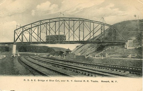
In other news, the truss bridge I had been eagerly awaiting for completing the mainline over the lower level tracks finally became available:
There were other bridges that would have been suitable, but this particular style is evocative (if less spindly) of the old trolley bridge that, when converted to a highway bridge, carried NY Route 31 over the railroad tracks between Lyons and Newark, and over which I passed many times when younger (though later than when this illustration was made - watch it!):

It is resting temporarily on the unfinished roadbed; some adjustment of the bridge and suppert piers will be necessary to align it with the level of the track. Even in its temporary position, it was worth the wait!
I've also assembled the turnouts and track for the rest of the lower industrial area, and once I have that soldered and installed I'll be able to get the mainline in as far as the east end of the yard.More importantly, Bryan and Fiona joined the operating crew as engineer trainees, and really enjoyed running one of the steamers and a couple of passenger cars back and forth over the completed mainline. I suggested that we pretend that we are showing railroad officials how much work has been done so far. That was certainly done in real life, although any tracklaying crew working at the rate I have would have been fired long ago!
In other news, the truss bridge I had been eagerly awaiting for completing the mainline over the lower level tracks finally became available:
There were other bridges that would have been suitable, but this particular style is evocative (if less spindly) of the old trolley bridge that, when converted to a highway bridge, carried NY Route 31 over the railroad tracks between Lyons and Newark, and over which I passed many times when younger (though later than when this illustration was made - watch it!):
It is resting temporarily on the unfinished roadbed; some adjustment of the bridge and suppert piers will be necessary to align it with the level of the track. Even in its temporary position, it was worth the wait!
Sunday, November 14, 2010
Layout Update #14: Lots of Paper Progress
Over the past month or so I took some time to consider what kind of trains - and how many - I wanted to run on the layout. Like many modelers, I'd like to have a mix of long-haul freight trains, local freights to work the various industries served by the railroad, and short- and long-distance passenger trains. When coming up with an operations plan, the questions to answer include:
1) Where are the trains coming from?
2) Where are they going?
3) How many of each are necessary?
For question one, there are three answers: west of the modeled area, east of the modeled area, and within the modeled area itself (specifically, the freight yard). For question two, the answer is much the same, although the destinations I envision include the lower industrial area and the various industry tracks around the freight yard. I include in this latter category such locations as the track where coal for the steam locomotives is delivered, and the RIP (Repair In Place) track where minor freight car repairs are made. (Generally speaking, an "industry" is any track where a railroad car can be picked up and dropped off. Among other things, it can be a factory, a track at the passenger station where additional passenger cars are kept, or a track representing a connection - interchange - with another railroad.)
Question three is a bit trickier. Given the relatively small size of the layout and the small size of my locomotive roster, plus the relatively few operators involved, I'm going to start by planning for a relatively small number of trains, as follows:
1) Eastbound long-haul freight
2) Westbound long-haul freight
3) Local train to service lower industrial area
4) Local train to service rural industrial area and points beyond (off layout)
5) Service of "yard area" industries
To get a better understanding of how the desired trains would run on the layout, i.e. how an actual section of railroad would operate, I drew up what is sometimes known as an "operations schematic." The goal is to "translate" the model trackplan into a representation of an actual stretch of railroad. With a continuous loop plan such as mine, you decide where to "snip" the loop and stretch it into a straight line. Here's what I came up with:

Laying out the route of the various planned trains onto the schematic made me aware of the heavy emphasis on the section of the layout between the east end of the yard and the east end of yard and the lower industrial/interchange section. (Part of me thinks that maybe I should have planned for a double mainline track on this part of the layout, but that most likely would not have been feasible given the minimum curve radius I wanted. This led me to think that perhaps I should have better options for arranging the west end of the yard, to allow more flexible operation from both ends of the yard in case the scheduled trains started piling up.
This noodling and doodling coincided with the growing sense that the design I had come up with for the main freight yard was vaguely dissatisfying. It provided the appropriate storage and functionality, but something didn't seem quite right about it; it didn't seem railroady.
This past Columbus Day weekend I had some time to kill before an overnight trip to Western New York to visit my parents. (Traveling overnight helps with traffic and really helps with the kids, who are actually very good travelers when awake but are perfect travelers when sleeping.) Laura and the kids were watching TV/napping, so I took an earlier printout of the layout plan and started doodling. This led to a trip to the basement and some test placement of turnouts, which convinced me that I could get away with making the main yard (blocks of cars for running east and west) double-ended, while providing a smaller adjacent yard for local and interchange traffic.
Here is the revised plan:

The good news is that I am only short a couple of turnouts, so the great increase in functionality (and, I hope, in realism) will come at relatively low expense. None of the track in this area had been laid anyway, so there is no loss of material or time either.
1) Where are the trains coming from?
2) Where are they going?
3) How many of each are necessary?
For question one, there are three answers: west of the modeled area, east of the modeled area, and within the modeled area itself (specifically, the freight yard). For question two, the answer is much the same, although the destinations I envision include the lower industrial area and the various industry tracks around the freight yard. I include in this latter category such locations as the track where coal for the steam locomotives is delivered, and the RIP (Repair In Place) track where minor freight car repairs are made. (Generally speaking, an "industry" is any track where a railroad car can be picked up and dropped off. Among other things, it can be a factory, a track at the passenger station where additional passenger cars are kept, or a track representing a connection - interchange - with another railroad.)
Question three is a bit trickier. Given the relatively small size of the layout and the small size of my locomotive roster, plus the relatively few operators involved, I'm going to start by planning for a relatively small number of trains, as follows:
1) Eastbound long-haul freight
2) Westbound long-haul freight
3) Local train to service lower industrial area
4) Local train to service rural industrial area and points beyond (off layout)
5) Service of "yard area" industries
To get a better understanding of how the desired trains would run on the layout, i.e. how an actual section of railroad would operate, I drew up what is sometimes known as an "operations schematic." The goal is to "translate" the model trackplan into a representation of an actual stretch of railroad. With a continuous loop plan such as mine, you decide where to "snip" the loop and stretch it into a straight line. Here's what I came up with:

Laying out the route of the various planned trains onto the schematic made me aware of the heavy emphasis on the section of the layout between the east end of the yard and the east end of yard and the lower industrial/interchange section. (Part of me thinks that maybe I should have planned for a double mainline track on this part of the layout, but that most likely would not have been feasible given the minimum curve radius I wanted. This led me to think that perhaps I should have better options for arranging the west end of the yard, to allow more flexible operation from both ends of the yard in case the scheduled trains started piling up.
This noodling and doodling coincided with the growing sense that the design I had come up with for the main freight yard was vaguely dissatisfying. It provided the appropriate storage and functionality, but something didn't seem quite right about it; it didn't seem railroady.
This past Columbus Day weekend I had some time to kill before an overnight trip to Western New York to visit my parents. (Traveling overnight helps with traffic and really helps with the kids, who are actually very good travelers when awake but are perfect travelers when sleeping.) Laura and the kids were watching TV/napping, so I took an earlier printout of the layout plan and started doodling. This led to a trip to the basement and some test placement of turnouts, which convinced me that I could get away with making the main yard (blocks of cars for running east and west) double-ended, while providing a smaller adjacent yard for local and interchange traffic.
Here is the revised plan:

The good news is that I am only short a couple of turnouts, so the great increase in functionality (and, I hope, in realism) will come at relatively low expense. None of the track in this area had been laid anyway, so there is no loss of material or time either.
Tuesday, September 28, 2010
Layout Update #13: One Summer Later
The subtitle is what I wrote in my layout notebook between the entry for April 24 and the next entry on - drum roll - September 16. On that day I managed to get the remaining cork roadbed sanded and ready to be painted prior to tracklaying, and did the initial cutting and fitting of half of the 3/16" cork sheet for the west (left) side of the yard.
Last weekend I managed to put in a fair bit of time in the trainroom, in between rounds of laundry, birthday parties, and painting swords that Fiona and Bryan picked up at the Maryland Renaissance Festival. Laundry and painting are also basement activities, so I didn't have too far to travel. The cork for the west end of the yard is glued down, although I will probably trim it back a bit from the mainline, and most of the track for the long interchange/staging section is down as well. The two turnouts forming the lefthand side of the lower industrial area are in place although not yet wired or attached to their ground throws, and part of the rural industrial track is a soldered and wired sub-assembly awaiting installation.


In the second picture you can see the arrangement for the "remote" mechanism for one of the industrial section turnouts, with the wire throw rod running in a plastic tube under the tracks to the layout edge. Because of space considerations there will be a fair amount of this kind of engineering required for the yard, so this is serving as a good practice run for the larger task ahead.
Overall there is not a huge amount of visible progress, although I did get the interchange/staging track secured last night. However, the weekend was more important for getting me back in the practice of construction, and in figuring out how to divide larger tasks into sub-tasks that can be fit into the "here and there" moments into which the bulk of my spare time is divided.
I did achieve a sentimental milestone a couple of hours ago, when I attached a terminal strip I had used on my previous layout to the underside of the benchwork to hold one end of the bus wire for the interchange/staging track power. This is the first official incorporation of a first layout element into the new project.
Here's the updated Track Progress Diagram:

Until next time!
Last weekend I managed to put in a fair bit of time in the trainroom, in between rounds of laundry, birthday parties, and painting swords that Fiona and Bryan picked up at the Maryland Renaissance Festival. Laundry and painting are also basement activities, so I didn't have too far to travel. The cork for the west end of the yard is glued down, although I will probably trim it back a bit from the mainline, and most of the track for the long interchange/staging section is down as well. The two turnouts forming the lefthand side of the lower industrial area are in place although not yet wired or attached to their ground throws, and part of the rural industrial track is a soldered and wired sub-assembly awaiting installation.
In the second picture you can see the arrangement for the "remote" mechanism for one of the industrial section turnouts, with the wire throw rod running in a plastic tube under the tracks to the layout edge. Because of space considerations there will be a fair amount of this kind of engineering required for the yard, so this is serving as a good practice run for the larger task ahead.
Overall there is not a huge amount of visible progress, although I did get the interchange/staging track secured last night. However, the weekend was more important for getting me back in the practice of construction, and in figuring out how to divide larger tasks into sub-tasks that can be fit into the "here and there" moments into which the bulk of my spare time is divided.
I did achieve a sentimental milestone a couple of hours ago, when I attached a terminal strip I had used on my previous layout to the underside of the benchwork to hold one end of the bus wire for the interchange/staging track power. This is the first official incorporation of a first layout element into the new project.
Here's the updated Track Progress Diagram:

Until next time!
Tuesday, July 13, 2010
Layout Update: OK, Technically Not a Layout Update
The advent of warm weather and the many demands of late spring and summer have, not surprisingly, put a damper on layout construction. In a response to a recent Facebook demand for update pictures, I suggested that one should look at the most recent update pictures and imagine various rearrangements of surface clutter. Sad but true, not that I haven't enjoyed the time spent outdoors.
In partial compensation, please direct your attention to the new blogroll category "Working on Their Railroads," featuring two very-well-built layouts and a couple of other sites of interest to anyone interested in model railroading. In the meantime, I am trying to practice incrementalism (see here and here), although the only real shortage is spare time or, to put it more directly, the ability to leverage what time I have into progress.
Wednesday, March 24, 2010
Layout Update #12: Belated Silver Spike Edition
I am very pleased to report, albeit nearly a month later, that I have commenced tracklaying! So far I have thirteen feet of mainline down, representing most of the rural section and extending to the lower level of the West Yard section, and secured to the roadbed using clear latex adhesive. To illustrate the progress, here is a by-now-familiar layout plan with installed track shown in solid lines (click the image to get a better view):

After a brief refresher course in soldering I feel pretty confident about the work I am doing, and that is backed up by what appears to be a consistent electrical connection to all of the track. Following standard practice I am soldering feeder wires to each section of track, which to this point has been 2.5-foot pieces of Atlas code 55 flextrack. The feeders in turn are attached to bus wires running underneath the benchwork using Scotchlok "suitcase connectors"; these have the advantage (from the point of view of a still-learning solderer) of being solder-free, although I understand there are different opinions as to their effectiveness and using soldered joints is invariably better. However, given the relatively small size of the layout I think I can get away with using them. There, I jinxed it.
Here are some views of the completed track:


In the first picture you can see, in the right foreground, two sets of feeders, one already soldered to the track and another waiting to be attached.
Here is a closeup of the turnout leading to the rural industrial trackage:

The points are moved using the not-very visible groundthrow to the left of the turnout. The black wire leads to the X-shaped "frog" of the turnout and takes power from one of two track wires depending on which way the turnout is positioned; without the ability to change the polarity of the frog a short circuit would result. The groundthrows and their attendant wiring are bulkier than anticipated and will pose engineering problems particularly in the yard (where a lot of turnouts will be laid out in close proximity to each other), but since I bought a lot of them I will work it out as I go along. I have already determined experimentally that I can run a length of stiff 22-gauge wire through a skinny coffee-stirrer straw over a relatively long distance to throw a turnout, but that will require a lot of pre-planning on my part since the wires will need to run under other tracks. The trackage heading into the lower industrial area on the yard sections will be the first test of that technique and I will try to document it.
In other developments, all of the beveled cork roadbed for the mainline is now in place, and I have begun measuring the slightly thinner sheet cork sections for the lower industrial area and, eventually, the freight yard.
Most importantly, I have brought a few engines home to run over the tracks! In the course of doing so I discovered that the wheelsets on the tender of one of my steam engines are out of gauge, which I discovered while running the engine through the turnout then confirmed using my NMRA gauge. The Atlas turnouts are notorious for being precision-engineered with little tolerance for out-of-gauge wheels, but so far only those wheels have posed a problem for any of the engines.
Until next time!
Random Running Glossary:
Code [X] - This refers to the height of the rail in thousandths of an inch. Code 55 track, for example, is .055" in height. The longtime "standard" for N scale, whcih I used on my first layout, is code 80, but the smaller the rail, the more realistic the appearance. I'll try to remember to take a picture of the two types of track side by side; the difference in appearance is substantial.
NMRA gauge - The National Model Railroading Association (NMRA) maintains an encyclopedic collection of standards and practices governing nearly all aspects of the hobby. One of the handiest tools I have (next to my absolutely indispensible Optivisor) is the Standards Gage, which includes most of the frequently-needed measurements on a single piece of flat metal.

After a brief refresher course in soldering I feel pretty confident about the work I am doing, and that is backed up by what appears to be a consistent electrical connection to all of the track. Following standard practice I am soldering feeder wires to each section of track, which to this point has been 2.5-foot pieces of Atlas code 55 flextrack. The feeders in turn are attached to bus wires running underneath the benchwork using Scotchlok "suitcase connectors"; these have the advantage (from the point of view of a still-learning solderer) of being solder-free, although I understand there are different opinions as to their effectiveness and using soldered joints is invariably better. However, given the relatively small size of the layout I think I can get away with using them. There, I jinxed it.
Here are some views of the completed track:
In the first picture you can see, in the right foreground, two sets of feeders, one already soldered to the track and another waiting to be attached.
Here is a closeup of the turnout leading to the rural industrial trackage:
The points are moved using the not-very visible groundthrow to the left of the turnout. The black wire leads to the X-shaped "frog" of the turnout and takes power from one of two track wires depending on which way the turnout is positioned; without the ability to change the polarity of the frog a short circuit would result. The groundthrows and their attendant wiring are bulkier than anticipated and will pose engineering problems particularly in the yard (where a lot of turnouts will be laid out in close proximity to each other), but since I bought a lot of them I will work it out as I go along. I have already determined experimentally that I can run a length of stiff 22-gauge wire through a skinny coffee-stirrer straw over a relatively long distance to throw a turnout, but that will require a lot of pre-planning on my part since the wires will need to run under other tracks. The trackage heading into the lower industrial area on the yard sections will be the first test of that technique and I will try to document it.
In other developments, all of the beveled cork roadbed for the mainline is now in place, and I have begun measuring the slightly thinner sheet cork sections for the lower industrial area and, eventually, the freight yard.
Most importantly, I have brought a few engines home to run over the tracks! In the course of doing so I discovered that the wheelsets on the tender of one of my steam engines are out of gauge, which I discovered while running the engine through the turnout then confirmed using my NMRA gauge. The Atlas turnouts are notorious for being precision-engineered with little tolerance for out-of-gauge wheels, but so far only those wheels have posed a problem for any of the engines.
Until next time!
Random Running Glossary:
Code [X] - This refers to the height of the rail in thousandths of an inch. Code 55 track, for example, is .055" in height. The longtime "standard" for N scale, whcih I used on my first layout, is code 80, but the smaller the rail, the more realistic the appearance. I'll try to remember to take a picture of the two types of track side by side; the difference in appearance is substantial.
NMRA gauge - The National Model Railroading Association (NMRA) maintains an encyclopedic collection of standards and practices governing nearly all aspects of the hobby. One of the handiest tools I have (next to my absolutely indispensible Optivisor) is the Standards Gage, which includes most of the frequently-needed measurements on a single piece of flat metal.
Wednesday, February 17, 2010
Layout Update #11: When the Mice are Away, the Cat Will Head to the Basement
Last week during the unplanned long staycation, Laura wisely signed up the kids for daycamp for both last Friday and Monday. The latter being Presidents' Day gave us a day at home without the kids, and I spent the bulk of it working on the layout and making more progress.
In particular, the mainline roadbed is done on most of the rural section and extends into the middle of the lower level on the yard section. Meanwhile, I also laid roadbed on the gradient around the engine terminal, and it is complete from the beginning of the gradient to the far right curve just before the beginning of the yard proper.
The first two pictures also show the roughed-in contour of the embankment that will take the upper level track to the bridge over the lower level tracks. The inspiration for that comes from the massive embankment the Lehigh Valley Railroad constructed to take its mainline at grade across the north part of Geneva, NY, on its way from New York to Buffalo. Although the embankment stops sloping rather abruptly near the bottom, I plan to cover that with a more gradual slope for a better transition.


Here you can see where the cork has to be specially cut and formed to accommodate turnouts. The work went a bit slower here because of the additional care required to keep the mainline nice and straight (I used the metal yardstick to align one half of the roadbed, then aligned the second half with the first) and lay out the turnout sections.
Most importantly, I also had to deal with a slight misalignment of the mainline with the engine terminal gradient resulting from slight yet cumulative errors in connecting and placing the paper sections of the printed trackplan onto the surface. Fortunately I was able to mark out the realigned track section last night, and this evening I laid about three more feet of the gradient roadbed after taking the pictures.
I also painted most of the tunnel roadbed black in preparation for (drum roll) laying track, and marked the rough locations of feeder wires with pushpins of the same color os the wires that will be soldered to the track. I also installed the bus wire under the rural section that will supply power to this section of the layout.

The sections of foam that are also painted black are those parts of the surface that could conceivably be seen by looking into the tunnel portals from outside. This side of the layout will have a relatively tall fascia section to match the elevation of the mountains over the tunnel, and while there will be openings for handling cars and engines and dealing with trouble, I plan to have hinged covers so light does not come out of the tunnel portals.
In a burst of optimism I brought two of my steam engines home from their temporary roundhouse at work (aka my desk drawer) for running on newly installed track. I chose the steamers rather than diesels because I prefer steam to diesel and, more importantly, everything I have read about these particular models (a 2-8-0 and 4-8-2) indicates that they are fussy about track alignment and are therefore good for evaluating trackwork.
Before I get any track down, however, I need to get in some soldering practice on some of my older and more expendable track. Nevertheless, we are moving closer to actual working track!
Slightly off topic, a discussion arose in the comments on the previous update about what I listen to while working, prompted by the spotting of an iPod dock in one of the pictures. Generally I hit Shuffle and get to work, but I am occasionally reminded that the ductwork from our central HVAC system runs into the trainroom and thence to the upper floors, as upstairs residents occasionally comment on the music wafting through the vents. In an incident that I am sure will eventually be considered universally amusing, my mother-in-law was the first to discover these acoustic properties of the ductwork, on Christmas night no less, as the appropriate-for-all-holidays music of Neil Young bid Merry Christmas to all, and to all a good night, followed by 45 seconds of guitar feedback.
In particular, the mainline roadbed is done on most of the rural section and extends into the middle of the lower level on the yard section. Meanwhile, I also laid roadbed on the gradient around the engine terminal, and it is complete from the beginning of the gradient to the far right curve just before the beginning of the yard proper.
The first two pictures also show the roughed-in contour of the embankment that will take the upper level track to the bridge over the lower level tracks. The inspiration for that comes from the massive embankment the Lehigh Valley Railroad constructed to take its mainline at grade across the north part of Geneva, NY, on its way from New York to Buffalo. Although the embankment stops sloping rather abruptly near the bottom, I plan to cover that with a more gradual slope for a better transition.
Here you can see where the cork has to be specially cut and formed to accommodate turnouts. The work went a bit slower here because of the additional care required to keep the mainline nice and straight (I used the metal yardstick to align one half of the roadbed, then aligned the second half with the first) and lay out the turnout sections.
Most importantly, I also had to deal with a slight misalignment of the mainline with the engine terminal gradient resulting from slight yet cumulative errors in connecting and placing the paper sections of the printed trackplan onto the surface. Fortunately I was able to mark out the realigned track section last night, and this evening I laid about three more feet of the gradient roadbed after taking the pictures.
I also painted most of the tunnel roadbed black in preparation for (drum roll) laying track, and marked the rough locations of feeder wires with pushpins of the same color os the wires that will be soldered to the track. I also installed the bus wire under the rural section that will supply power to this section of the layout.
The sections of foam that are also painted black are those parts of the surface that could conceivably be seen by looking into the tunnel portals from outside. This side of the layout will have a relatively tall fascia section to match the elevation of the mountains over the tunnel, and while there will be openings for handling cars and engines and dealing with trouble, I plan to have hinged covers so light does not come out of the tunnel portals.
In a burst of optimism I brought two of my steam engines home from their temporary roundhouse at work (aka my desk drawer) for running on newly installed track. I chose the steamers rather than diesels because I prefer steam to diesel and, more importantly, everything I have read about these particular models (a 2-8-0 and 4-8-2) indicates that they are fussy about track alignment and are therefore good for evaluating trackwork.
Before I get any track down, however, I need to get in some soldering practice on some of my older and more expendable track. Nevertheless, we are moving closer to actual working track!
Slightly off topic, a discussion arose in the comments on the previous update about what I listen to while working, prompted by the spotting of an iPod dock in one of the pictures. Generally I hit Shuffle and get to work, but I am occasionally reminded that the ductwork from our central HVAC system runs into the trainroom and thence to the upper floors, as upstairs residents occasionally comment on the music wafting through the vents. In an incident that I am sure will eventually be considered universally amusing, my mother-in-law was the first to discover these acoustic properties of the ductwork, on Christmas night no less, as the appropriate-for-all-holidays music of Neil Young bid Merry Christmas to all, and to all a good night, followed by 45 seconds of guitar feedback.
Labels:
layout progress,
N scale,
neil young
Thursday, February 11, 2010
Layout Update #10: I Hear That Terrain a-Comin'
After yesterday's respite from shoveling snow we got socked with another foot of snow and high winds, which continue to roar outside our house as I write this. Indoor activities thus were the order of the day, and while Laura put in a few hours of work upstairs and the kids busied themselves with craft projects and the Big Blue Babysitter, I spent a ton of time in the basement and made great progress on a couple of fronts.
Much of the progress was actually made possible by being able to put in a few hours here and there over the past few days and even over the last couple of weeks, during which I was able to do a fair amount of prep work for the actual laying of track.
The first thing I did was get some landscape work done, specifically the bed of a creek on the transition section. A few weeks previously, I had used part of my Christmas gift certificate to get a couple of cut stone culvert/abutment sets. Using two-inch-thick foam insulation board not only allows the construction of hills above track level (not to mention track gradients between levels of foam), but also the creation of terrain below track level. Hopefully this will reduce the "tabletop" feel of the layout.
I found two reasonably plausible locations for culverts: on the transition section, and on the rural section near the entrance to the lower tunnel portal. Using the culvert pieces as a template, I marked their location on the foam, then drew both the bed of the creek that would pass through the culvert underneath the main line and the approximate start of the downward slope of the banks of the creek. From there I used primarily a serrated paring knife emergency-requisitioned from the kitchen and carved a rough outline of the terrain:

I must say that this was incredibly fun, and while I am no artist, I was reminded of the sense that sculptors can have of seeing the finished work within an uncut block of stone. "Hey, that looks how I thought it would look!" It was a great introduction to basic scenery (I had done almost none on my high-school-era layout and absolutely none with foam) and a good test bed for later work, of which more below.
After an interlude of a couple of weeks during which normal life reasserted itself and kept me out of the basement, the monster snowstorms and resulting time off from work gave me some time to put in a few more hours in the train room in between shoveling, snow fort construction and sledding. Inspired and encouraged by the first culvert/creek location, I next applied the terraforming knife to the rural section, where in addition to a creek and culvert, I carved out a lake to nestle at the foot of the main hill/mountain terrain. My inspiration for this was Bald Mountain Pond, a small, narrow body of water just outside of Old Forge, New York in the Adirondacks. It lies at the foot of Bald Mountain and features some impressive rock outcrops as well as tree trunks in the water and other model-worthy items. Just the place for my N scale deer to forage!

The same day I roughed in the lake, I applied Woodland Scenics Foam Putty to the joints between foam pieces where trackwork would be located, to provide a smooth transition between sections. There are a couple of areas where I am going to need to sand the foam somewhat for a better fit, but overall the surface is ready for roadbed.
With that preparation work completed, I began laying cork roadbed for the mainline on the rural section. Not only was the rural section ready for roadbed, but I could begin the work inside the tunnel and thus hide any unsightly rookie mistakes, as this was my first experience with using latex caulk to secure cork roadbed to foam. Fortunately the only thing I needed to adjust was the amount of caulk used (less) and the technique for applying it (a thin bead for each half rather then a slightly larger bead down the middle). About 75% of the rural roadbed is down; I was limited by the need to even out the foam joint between the rural and transition sections, the need to lower the bridge abutments on the upper grade, and, on a more basic engineering level, a relative shortage of pushpins to hold the cork in place while the caulk dried. Fortunately the caulk dries pretty quickly so I envision the rest of the work taking place in stages.


In the first picture you can barely see the end section of the roadbed on the upper grade hanging loose on the foam. This shows both the technique I employed of staggering the two sections of roadbed to help with alignment on curves, and the need to hold off on further roadbed work until I lower the bridge abutments to align with the top of the foam.
Energized by the more visible progress (carving terrain is fun but it's still pink!) I decided that since the mainline roadbed on the engine terminal section had to wait for the surrounding terrain to be roughed in, by God I would rough it in. Realizing that a paring knife was inadequate for the much larger task of shaping hills and embankments, I got the Stanley Surform rasp out of the toolbox and got to work.
First, however, I drew the "top terrain" line on the foam where I wanted the gradient to end. In most places I tried to design for a 45-degree or less slope, since that is relatively more realistic than a Cliffs of Dover approach, but where that was not possible I am planning a combination of rock outcroppings and retaining walls.
Second, following a tip I picked up from one of the discussion groups, I rubbed my hands and clothing with an anti-static dryer sheet to help reduce the possibility of my transformation into the Abominable Foam Dust Man. Not only did it keep much of the dust from clinging, I smelled clothesline fresh!
I did do some initial shaping and bulk foam-cutting with the paring knife, but for the most part I used the rasp to create nicely-rounded slopes and embankments, with frequent pauses to vacuum the foam dust away. I am very pleased with the initial results:


Before laying roadbed on this section I need to apply some putty to fill the gaps on either side of the right-of-way, but apart from that nearly all of the roadbed can be laid down as soon as I find the time, which may come as early as this weekend. Based on my initial work on the rural section I think this should proceed fairly quickly.
The next steps after laying the roadbed are 1) painting the roadbed flat black and 2) cutting any necessary channels in it to allow wires to pass under the track. The first is fairly straightforward: railroads usually laid track on a prepared surface of crushed stone and, in the steam era, coal cinders from locomotives. In addition, flat black is a much less attention-grabbing color than the speckled brown of cork roadbed. The second is an engineering requirement of the turnouts (aka switches), which require power to be run to the "frog" of the turnout - the X-ish shaped piece near where the tracks diverge at left in this picture:

Hopefully I will have another post up soon with more progress!
Much of the progress was actually made possible by being able to put in a few hours here and there over the past few days and even over the last couple of weeks, during which I was able to do a fair amount of prep work for the actual laying of track.
The first thing I did was get some landscape work done, specifically the bed of a creek on the transition section. A few weeks previously, I had used part of my Christmas gift certificate to get a couple of cut stone culvert/abutment sets. Using two-inch-thick foam insulation board not only allows the construction of hills above track level (not to mention track gradients between levels of foam), but also the creation of terrain below track level. Hopefully this will reduce the "tabletop" feel of the layout.
I found two reasonably plausible locations for culverts: on the transition section, and on the rural section near the entrance to the lower tunnel portal. Using the culvert pieces as a template, I marked their location on the foam, then drew both the bed of the creek that would pass through the culvert underneath the main line and the approximate start of the downward slope of the banks of the creek. From there I used primarily a serrated paring knife emergency-requisitioned from the kitchen and carved a rough outline of the terrain:
I must say that this was incredibly fun, and while I am no artist, I was reminded of the sense that sculptors can have of seeing the finished work within an uncut block of stone. "Hey, that looks how I thought it would look!" It was a great introduction to basic scenery (I had done almost none on my high-school-era layout and absolutely none with foam) and a good test bed for later work, of which more below.
After an interlude of a couple of weeks during which normal life reasserted itself and kept me out of the basement, the monster snowstorms and resulting time off from work gave me some time to put in a few more hours in the train room in between shoveling, snow fort construction and sledding. Inspired and encouraged by the first culvert/creek location, I next applied the terraforming knife to the rural section, where in addition to a creek and culvert, I carved out a lake to nestle at the foot of the main hill/mountain terrain. My inspiration for this was Bald Mountain Pond, a small, narrow body of water just outside of Old Forge, New York in the Adirondacks. It lies at the foot of Bald Mountain and features some impressive rock outcrops as well as tree trunks in the water and other model-worthy items. Just the place for my N scale deer to forage!
The same day I roughed in the lake, I applied Woodland Scenics Foam Putty to the joints between foam pieces where trackwork would be located, to provide a smooth transition between sections. There are a couple of areas where I am going to need to sand the foam somewhat for a better fit, but overall the surface is ready for roadbed.
With that preparation work completed, I began laying cork roadbed for the mainline on the rural section. Not only was the rural section ready for roadbed, but I could begin the work inside the tunnel and thus hide any unsightly rookie mistakes, as this was my first experience with using latex caulk to secure cork roadbed to foam. Fortunately the only thing I needed to adjust was the amount of caulk used (less) and the technique for applying it (a thin bead for each half rather then a slightly larger bead down the middle). About 75% of the rural roadbed is down; I was limited by the need to even out the foam joint between the rural and transition sections, the need to lower the bridge abutments on the upper grade, and, on a more basic engineering level, a relative shortage of pushpins to hold the cork in place while the caulk dried. Fortunately the caulk dries pretty quickly so I envision the rest of the work taking place in stages.
In the first picture you can barely see the end section of the roadbed on the upper grade hanging loose on the foam. This shows both the technique I employed of staggering the two sections of roadbed to help with alignment on curves, and the need to hold off on further roadbed work until I lower the bridge abutments to align with the top of the foam.
Energized by the more visible progress (carving terrain is fun but it's still pink!) I decided that since the mainline roadbed on the engine terminal section had to wait for the surrounding terrain to be roughed in, by God I would rough it in. Realizing that a paring knife was inadequate for the much larger task of shaping hills and embankments, I got the Stanley Surform rasp out of the toolbox and got to work.
First, however, I drew the "top terrain" line on the foam where I wanted the gradient to end. In most places I tried to design for a 45-degree or less slope, since that is relatively more realistic than a Cliffs of Dover approach, but where that was not possible I am planning a combination of rock outcroppings and retaining walls.
Second, following a tip I picked up from one of the discussion groups, I rubbed my hands and clothing with an anti-static dryer sheet to help reduce the possibility of my transformation into the Abominable Foam Dust Man. Not only did it keep much of the dust from clinging, I smelled clothesline fresh!
I did do some initial shaping and bulk foam-cutting with the paring knife, but for the most part I used the rasp to create nicely-rounded slopes and embankments, with frequent pauses to vacuum the foam dust away. I am very pleased with the initial results:
Before laying roadbed on this section I need to apply some putty to fill the gaps on either side of the right-of-way, but apart from that nearly all of the roadbed can be laid down as soon as I find the time, which may come as early as this weekend. Based on my initial work on the rural section I think this should proceed fairly quickly.
The next steps after laying the roadbed are 1) painting the roadbed flat black and 2) cutting any necessary channels in it to allow wires to pass under the track. The first is fairly straightforward: railroads usually laid track on a prepared surface of crushed stone and, in the steam era, coal cinders from locomotives. In addition, flat black is a much less attention-grabbing color than the speckled brown of cork roadbed. The second is an engineering requirement of the turnouts (aka switches), which require power to be run to the "frog" of the turnout - the X-ish shaped piece near where the tracks diverge at left in this picture:

Hopefully I will have another post up soon with more progress!
Subscribe to:
Posts (Atom)